

Heavy Copper PCB Manufacturer
Heavy Copper PCB & Custom Copper Clad PCB Board Solutions
Benlida manufactures custom heavy copper PCBs for power electronics. Share your fabrication files, layer-by-layer copper requirements, quantity, and operating conditions to discuss the construction and quotation.
Specify finished copper on each layer
Define current, voltage drop, and temperature rise
Include vias, connectors, and cooling conditions
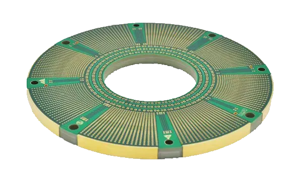
What Is a Heavy Copper PCB?
Heavy copper PCB commonly refers to a board with circuit copper around 3 oz/ft² or thicker. The threshold is a commercial convention, so the drawing should specify the copper requirement for each layer.
At the same current, trace length and width, and cooling conditions, thicker copper can reduce temperature rise by lowering electrical resistance. This can help improve reliability in applications where overheating is a concern.
Benlida manufactures custom heavy copper PCBs for power electronics. Tell us your layer-by-layer copper requirements, board stack-up, and operating conditions so we can discuss your project.
Copper weight describes mass per unit area. Nominally, 1 oz/ft² is approximately 35 μm, and 3 oz/ft² is approximately 105 μm. These conversions do not define a finished-board minimum. State starting foil, finished copper, and required tolerances separately. Specify plated-hole wall copper independently from surface copper.
For the broader fabrication scope, see our PCB manufacturing services.
Our Heavy Copper Manufacturing Capabilities
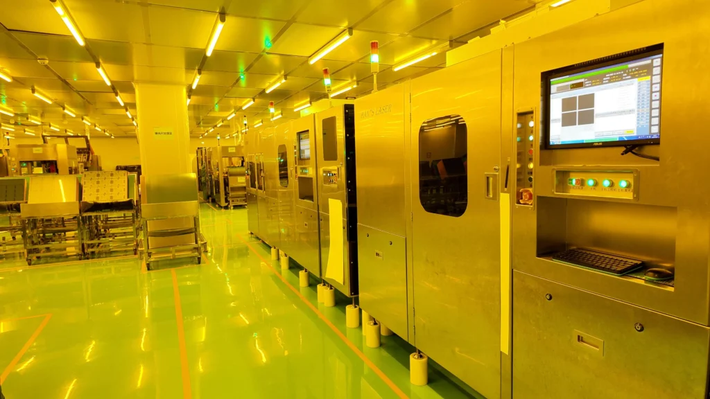
Benlida offers reliable solutions for heavy copper PCB manufacturing services with advanced production facilities, providing services on copper thicknesses ranging from 3 oz to 6 oz as standard and 20 oz for custom designs. As a trusted heavy copper PCB supplier, we offer multilayer construction, precision drilling, various surface finishes, and OEM/ODM services to meet the requirements of high-power and high-reliability applications.
Copper Thickness
3–6 oz standard; custom heavy copper options available (up to 20 oz on request)
Minimum Trace Width/Spacing
≥150 μm (6 mil) typical for heavy copper
Aspect Ratio
Up to 8:1 depending on structure
Layer Alignment Tolerance
±75 μm typical
Solder Mask
High-temperature resistant solder mask
Via Technology
Through-hole, filled vias, heavy copper vias
OEM/ODM
available
Board Thickness
0.8–6.0 mm standard; thicker constructions available
Minimum Drill Size
≥0.3 mm (12 mil); precision drilling
Multilayer Capability
Up to 12 layers or more
Review the related multilayer PCB considerations when defining the stack-up.
Surface Finish Options
HASL, Lead-Free HASL, ENIG, OSP, Immersion Silver, Immersion Tin
Compare surface finish options in our PCB surface finish guide.
Surface Roughness Control
Optimized for adhesion and performance
MOQ
1pcs
Packaging
ESD Protection Materials, Moisture barrier bags, Bubble wrap, Corrugated cartons
Current and Thermal Requirements
Copper weight alone does not define a safe current rating. Describe the complete power path and operating conditions when requesting a quote. Any requested electrical or thermal analysis needs a separately agreed scope.
- Current profile: continuous and peak current, pulse duration, duty cycle, and operating sequence.
- Conductor geometry: finished copper, width, length, layer location, neck-downs, pads, and plane transitions.
- Electrical and temperature limits: allowable voltage drop, temperature rise, ambient temperature, and nearby heat sources.
- Connections: plated holes, via groups, terminals, connectors, and the weakest section in the current path.
- Cooling: enclosure, airflow, heat sinks, interface materials, mounting, and board orientation.
- Validation: the design owner, intended calculation or measurement method, operating cases, and acceptance criteria.
Heavy Copper PCB Design Checklist
Use this checklist before releasing fabrication files. It highlights design inputs and manufacturing questions; it does not replace electrical, thermal, or product-level validation.
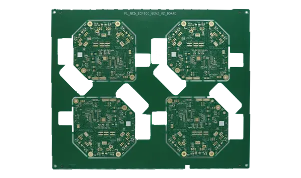
Start with conductor geometry, voltage requirements, materials, and copper distribution.
Size the Complete Current Path
Review finished width, copper thickness, length, layer location, temperature rise, and voltage drop. Include neck-downs, pads, vias, and connectors.
Choose Copper for the Requirement
Compare copper thickness with wider routing, additional conductors, and cooling options. Consider etching limits, resin fill, board size, and cost together.
Separate Spacing Requirements
Manufacturing spacing, electrical clearance, and creepage are different requirements. Provide working and transient voltages, material data, environment, altitude, and the applicable product requirements for insulation review.
Review Corners and Transitions
Avoid abrupt neck-downs where practical. Assess local current concentration and the minimum finished width around pads, corners, and plane transitions.
Review Expansion and Lamination
Consider laminate expansion, resin fill, copper balance, hole structure, and assembly temperature cycles. Set validation requirements for delamination and interconnect risks.
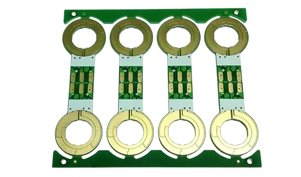
Then review interconnects, stack-up, manufacturing limits, and measurable acceptance requirements.
Design Via Groups as a Network
Specify finished hole size, hole-wall copper, spacing, and connection geometry. Parallel vias may carry unequal current; evaluate local heating and the complete interconnect path.
Define the Layer Stack-up
Identify power, ground, and signal layers, return paths, dielectric thicknesses, copper weights, and symmetry. Review electrical and manufacturing requirements together.
Confirm Manufacturability
Review copper thickness, line and space, finished holes, resin fill, solder mask coverage, and board dimensions as one construction. Resolve exceptions before fabrication release.
Specify Measurable Surface Requirements
Where roughness or plating is critical, define the surface, measurement method, location, tolerance, and acceptance criteria. Keep circuit copper and final finish requirements separate.
For a detailed discussion, read the heavy copper PCB design guide.
Heavy Copper PCB Advantages
Copper clad PCB boards with heavy copper layers feature great electrical, thermal, and mechanical properties suitable for challenging electronic applications. Unlike regular PCBs, the Heavy Copper PCBs have better current-carrying capacity, heat dissipation capabilities, and reliability due to their design features.
High Current Carrying Capacity
The Heavy Copper PCBs consist of copper thickness and enable them to conduct higher currents without generating too much heat. Hence, the Heavy Copper PCBs are useful for devices requiring a stable power supply.
Superior Heat Dissipation
The robust copper structure of a copper clad PCB board enhances heat dissipation by spreading heat more efficiently across the PCB. This reduces hotspots, improves system stability, and helps minimize the need for additional cooling solutions.
Enhanced Mechanical Strength
With heavy copper traces and planes on a PCB, there is improved mechanical robustness of the printed circuit board because of increased resistance to vibrations, heat, and tough environments. Heavy copper printed circuit boards are used in various industries like automobile, aerospace, and more.
Improved Reliability and Longevity
Because of the reduced electrical resistance and thermal stress, heavy copper PCBs offer reliability and longevity. Their performance remains stable at high current, high temperature, and under difficult operating conditions.
Simplified Circuit Design
The high current-carrying capacity of each trace eliminates the need for parallel routing or an extra layer of the PCB.
Better Resistance to Thermal Cycling
Heavy Copper PCBs are known to withstand thermal cycling well, thereby providing consistent functionality in applications that have many power cycles and difficult operating conditions.
Higher Power Density
Because of the heavy copper construction, high currents can be delivered in small spaces, making it possible to design high-power-density boards without sacrificing functionality, reliability, and thermal dissipation capacity.
Reduced Risk of Failure
The strong build with copper assures no issues like degradation of trace, delamination, and failure of via; hence, assuring efficient functioning of the PCB in critical applications.
Flexibility for Harsh Environments
Heavy Copper PCBs are capable of functioning successfully in conditions of extreme temperature, humidity, vibration, and even chemical exposure.
Heavy Copper PCB Manufacturing Process
Our company manufactures heavy copper PCBs using a detailed process that entails materials preparation, inner/outer layer imaging, lamination, drilling, copper plating, surface finishing, and inspection. This ensures that our heavy copper printed circuit boards have well-defined circuitry.
Heavy copper printed circuit board products from Benlida are manufactured using superior technology and quality control. Therefore, our customers benefit from printed circuit boards with good electrical and thermal conductivity.
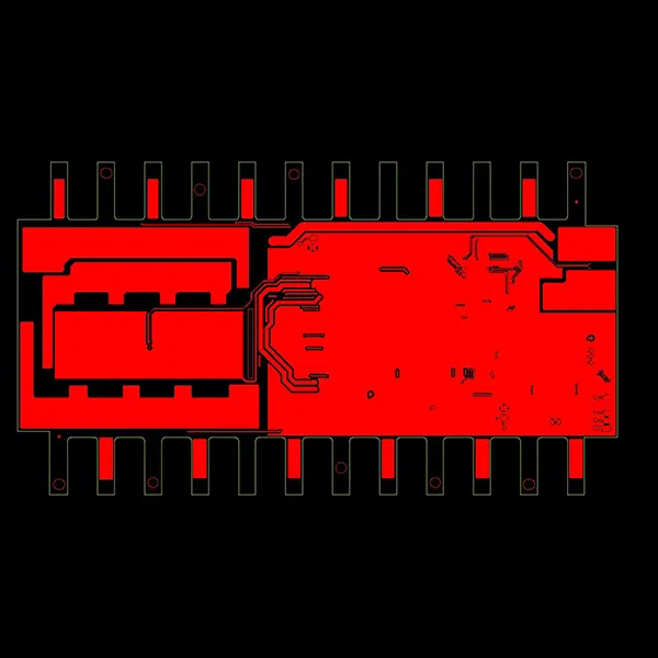
1
Material Preparation
Select high-performance base materials, including high-Tg laminates and 3 oz or thicker copper foil, to ensure excellent electrical performance, thermal management, and long-term reliability.
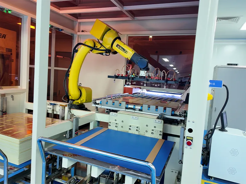
2
Inner Layer Imaging & Etching
Circuit patterns are precisely transferred onto the copper layers using photolithography, followed by controlled etching to produce accurate trace geometries in thick copper.
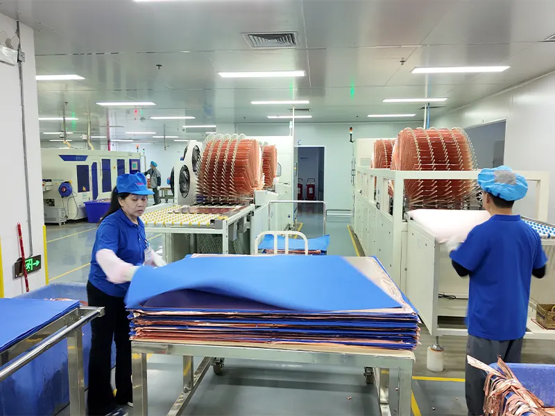
3
Layer Lamination
Multiple PCB layers are precisely stacked and laminated under controlled heat and pressure to create strong bonds and ensure a void-free, highly reliable multilayer structure.
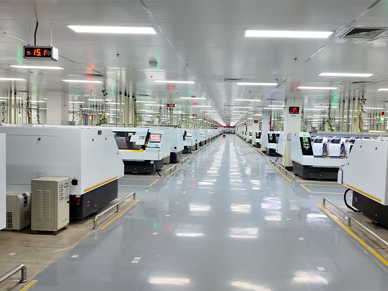
4
Drilling & Via Formation
High-precision mechanical or laser drilling creates accurate vias and holes, ensuring reliable interlayer connections and precise alignment in thick copper multilayer PCBs.
5
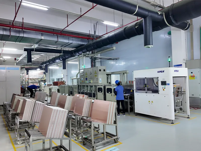
Copper Plating
Electroplating deposits additional copper onto vias and traces, enhancing conductivity, increasing copper thickness, and ensuring reliable interlayer connections.
6
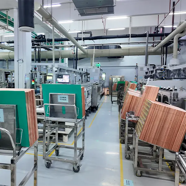
Outer Layer Patterning
The final circuit pattern is formed through precision imaging and controlled etching, ensuring accurate trace geometry and consistent quality in heavy copper PCBs.
7
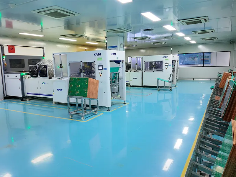
Surface Finish
Apply surface finishes such as HASL, ENIG, or Immersion Silver to protect exposed copper, improve corrosion resistance, and ensure excellent solderability.
8
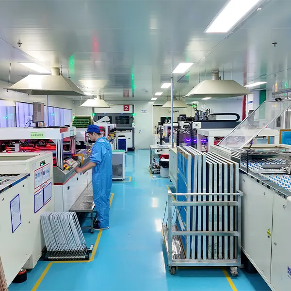
Solder Mask & Silkscreen
Apply a high-temperature solder mask to protect the PCB surface and add silkscreen markings for clear component identification and assembly guidance.
9
Routing & Profiling
The PCB is separated into its final dimensions using precision CNC routing or V-scoring, ensuring accurate outlines and clean, smooth edges.
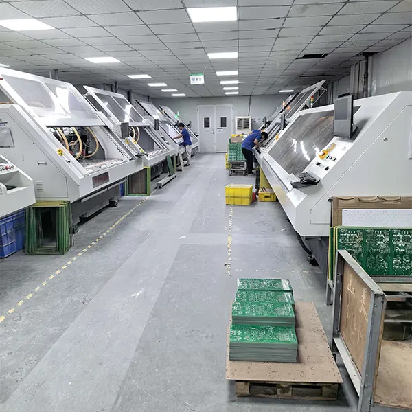
10
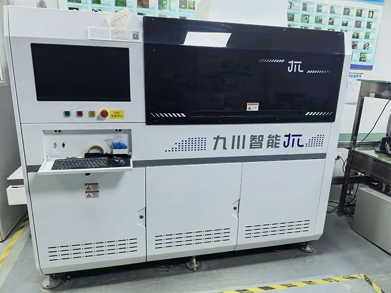
Testing & Inspection
Perform comprehensive inspections, including electrical testing, AOI, and X-ray inspection, to verify circuit integrity, detect defects, and ensure reliable internal structures.
For material context, see our FR-4 PCB page.
Product Testing & Quality Control
To ensure the stability and reliability of Heavy Copper PCB products in high-current and high-power applications, Benlida implements a comprehensive quality control system covering material inspection, production monitoring, and final testing. As experienced heavy copper PCB manufacturers, we apply strict inspection procedures to maintain consistent quality and reliable performance.
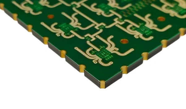
Electrical Performance Testing
Electrical testing is conducted to check the performance of the circuits for proper connection and insulation.
AOI (Automated Optical Inspection)
The AOI testing procedure involves automatic scanning of the PCB circuits to detect any possible open circuits, shorts, and problems with patterns.
X-Ray Inspection
X-Ray inspection is performed to examine internal structures, including multilayer connections, for quality, and hidden defects, ensuring reliable internal performance.
Copper Thickness and Structure Inspection
Copper thickness, trace structures, and critical dimensions are carefully controlled to ensure Heavy Copper PCB products meet required specifications and performance standards.
Final Quality Inspection
Prior to shipment, all PCBs are subjected to a thorough inspection process, which includes visual inspection, dimension verification, and performance testing to guarantee reliable quality.
See our quality control overview for related inspection information.
Why Choose Us?
Professional Manufacturing
Through our wide experience in the manufacture of heavy copper printed circuit boards, Benlida is able to offer quality solutions thanks to modern manufacturing technologies and high-quality standards.
Flexible Customization Capability
We support standard copper thickness from 3 oz to 6 oz and custom heavy copper designs up to 20 oz, along with multilayer structures, various surface finishes, and OEM/ODM services to meet different project requirements.
Strict Quality Control System
We make sure that we complete quality checks through AOI, X-ray inspection, and electrical testing throughout the process, from materials to final products.
Reliable Manufacturing Partner
As one of the trusted heavy copper PCB manufacturers, we support prototype and mass production with efficient delivery and customized solutions to help customers achieve their PCB development goals.
Heavy Copper PCB vs. MCPCB Comparison
Aluminum-Backed MCPCB, Copper-Core MCPCB, and Heavy Copper PCB are designed for different thermal and electrical requirements. As one of the experienced heavy copper PCB manufacturers, Benlida provides reliable PCB solutions, including high-performance designs based on advanced copper clad PCB board structures for demanding applications.
| Comparison Item | Aluminum-Backed MCPCB | Copper-Core MCPCB | Heavy Copper PCB |
|---|---|---|---|
| Structure | Aluminum base layer with copper circuit layer for effective heat dissipation | Copper core layer provides enhanced thermal conductivity | Thick copper layers on inner or outer layers improve current capacity and reliability |
| Copper Thickness | Usually 1–3 oz | Usually 1–3 oz | 3–6 oz standard, with custom options available up to 20 oz |
| Thermal Performance | Good thermal management for general applications | Better heat transfer due to copper core structure | Excellent heat dissipation through thick copper layers |
| Current Capacity | Suitable for low to medium current applications | Supports higher power requirements than aluminum-backed MCPCB | Designed for high-current and high-power applications |
| Design Flexibility | Commonly used for simple thermal applications | Suitable for thermal-critical designs | Supports multilayer structures and complex high-current circuits |
| Typical Applications | LED lighting, automotive lighting | Power modules, high-power LEDs, thermal-sensitive electronics | Power electronics, industrial equipment, automotive, renewable energy systems |
For lighting projects, explore our LED PCB page.
Heavy Copper PCB Applications
Heavy Copper PCBs are widely used in industries that require high current carrying capacity, excellent thermal management, and long-term reliability. As experienced heavy copper PCB manufacturers, Benlida provides reliable Heavy Copper PCB solutions based on high-quality copper clad PCB board materials to meet the needs of high-power applications and demanding operating environments.
Power Electronics
Heavy Copper PCBs are commonly used in power modules, inverters, and power conversion equipment. Their enhanced current capacity and heat dissipation capabilities help ensure stable and efficient system operation.
Automotive Electronics
For electric cars, motor controllers, and battery management systems, Heavy Copper PCBs prove to be very reliable and offer good thermal properties, which are required in the automotive environment.
Industrial Equipment
Heavy Copper PCBs support industrial automation equipment, motor drives, and control systems where high current handling and long-term operational stability are essential.
Renewable Energy Systems
Heavy Copper PCBs are suitable for solar inverters, energy storage systems, and power management equipment, providing reliable circuit performance for high-power energy applications.
Aerospace & High-Reliability Applications
With enhanced mechanical strength and resistance to harsh conditions, Heavy Copper PCBs meet the reliability requirements of aerospace and other mission-critical applications.
Heavy Copper PCB FAQ
The term commonly describes a PCB with circuit copper around 3 oz/ft² or thicker. It is a commercial description, not a universal acceptance specification. A fabrication drawing should identify starting copper, finished copper, layer locations, and tolerances. This page concerns finished bare PCBs rather than copper-clad laminate stock.
Specify the starting foil and finished copper requirement for each layer, including any minimum thickness and tolerance. The manufacturable combination also depends on geometry, holes, materials, and stack-up. Ask for confirmation of your complete construction instead of assuming that every copper weight is available in every structure.
There is no safe current rating based only on copper weight or the number of layers. Required inputs include finished conductor dimensions, length, layer position, voltage drop, allowable temperature rise, load profile, cooling, vias, and connectors. The complete current path needs an appropriate design assessment and validation.
Mixed copper requirements should be specified layer by layer. Their feasibility depends on the material system, copper balance, lamination, etching, and hole structure. State starting and finished copper separately where relevant, and request confirmation of the complete stack-up before releasing the fabrication files.
At the same current, trace length and width, and cooling conditions, thicker copper can reduce resistance, conduction loss, and temperature rise. It can also help spread heat. This can help improve reliability where overheating is a concern. Material selection, interconnects, and the complete thermal path still need evaluation.
No. Thicker copper can improve heat spreading within the board, but heat still needs a path to the environment. Dielectrics, interfaces, heat sinks, airflow, enclosure design, and nearby heat sources influence temperature. Evaluate the full thermal path under the intended load and ambient conditions.
Heavy copper describes the electrical conductor thickness. A metal-core PCB describes a substrate construction that includes a metal base and, in an insulated structure, a dielectric between the circuit and base. The categories can overlap. Compare the circuit copper, dielectric thermal resistance, insulation, and heat-sink interface for your design.
Potential applications include power converters, motor drives, and power-distribution circuits. Selection depends on current paths, voltage requirements, cooling, connections, and the operating environment. An application name alone does not establish suitability; the intended design and its validation requirements need to be assessed.
List the required visual, dimensional, electrical, and copper-thickness checks, with sampling and acceptance criteria. If you need microsections, X-ray, or other specialized evaluation, request confirmation of suitability and availability. Bare-board electrical testing is different from loaded current, temperature-rise, or assembled-product functional testing.
Prepare the fabrication data, drill files, fabrication drawing, stack-up, layer-by-layer copper requirements, material, finished thickness, surface finish, quantity, and revision. Include critical tolerances and required inspections. State the available file format in your enquiry so that the submission method can be confirmed before transferring the package.
Copper requirements, board area, layer structure, material availability, fabrication complexity, inspection scope, and quantity can affect the quotation and schedule. A prototype and a production order may have different cost drivers. Confirm minimum quantity, any setup charges, and the delivery schedule for the specific construction.
Identify the board revision and keep the fabrication files, stack-up, and order requirements consistent. If copper, material, dimensions, holes, or quantity change, request confirmation of the revised construction, price, and schedule before manufacture. A previous quotation should not be assumed to cover a changed specification.
Request a Heavy Copper PCB Quote
Send your project requirements to Benlida to discuss a heavy copper PCB quotation. Start with the board revision, quantity, stack-up, and copper requirements. State your available file format and any special inspection or delivery requirements.
Prepare Your Fabrication Package
- Gerber or ODB++ data, with the available format stated in the enquiry.
- Drill files and fabrication drawing.
- Stack-up, material, finished board thickness, and outline dimensions.
- Starting and finished copper requirements for each layer.
- Hole details, surface finish, solder mask, and critical tolerances.
- Quantity, revision, required inspections, and requested delivery date.
If assembly is also required, list it separately and identify the available BOM, placement data, and assembly requirements.
If your project also requires assembly, see our PCB assembly services.
For a current-path question, include the inputs listed in the Current and Thermal Requirements section. State any confidentiality requirements in the enquiry and confirm the file-transfer method before sending sensitive design files.